|
Doppler on 432 MHz First
what we have to remind on 432 (and up much more) is the Doppler shift. The
Doppler shift can get as high as 1KHz on 432 MHz. So
I knew of several qso which failed by not paying
attention to this. We have to see different cases: 1. Station
A is
calling CQ on 432,010. His program tells him a Doppler shift of +600Hz (he
has moonrise and moon in the east). So he is turns
his RIT to +600Hz and hears his echoes clear. Station
B has
the moon in the west and a Doppler of -300Hz. Hi turns his RIT to -300Hz and
hears his echoes. B now
turns his VFO-knob and hears A (with rit at -300Hz)
he can reply and A hears B on the qrg where A hears
his echoes. ----That’s fine for random qso. |
|
|
2. in skeds : In
every sked you should announce your TX qrg. Like 1. A TX on 010
with RIT. B answers as described. What if you don’t hear A in sked. Set your TX on sked QRG 010 and use
your RIT to find A. VK3UM planner shows you all 3 doppler
shifts between you and the DX station (if selected). For example : A_Home-A_Home +567 A_Home-B_DX -165 B_DX-B_DX -1096 If both have no Rit activated A hears his echoes 567 Hz above his TX QRG B hears his echoes 1096Hz below his TX QRG A hears B & B hears A 165 below their TX qrgs So for a sked both A and B set their TX on 010 and
with the RIT at -165HZ they will hear each other. The WSJT program shows different Doppler shifts depending if there is
a locator put in the field Grid. If grid is blank you see Doppler home-home.
If Grid is filled by the grid locator of the DX Station, the Doppler shift
home-DX is shown. That’s a bit confusing, but ok. |
|
|
3. This time we count the frequency like a
viewer/listener on the moon (Moon
RX) will see it. The qrg on the moon is for
everyone added half on the own Doppler effect. Now we have the following situation: Two stations will run a sked on 432,1000 MHz Station A has a dopplershift
of +600Hz (for own echoes) Station B has a dopplershift
of -800Hz (for
own echoes) Station A tunes
his TX to 432,0997 MHz =432,1000 MHz – ½*600Hz So his TX signal will appear at the moon on 432,1000 MHz. To hear his echoes Station A tunes the RX to 432,0997 + 600Hz
= 432,1003 MHz Station B tunes
his TX to 432100,4 MHz =432,1000 MHz + ½*800Hz So his TX signal will appear at the moon on 432,1000 MHz. To hear his echoes Station A tunes the RX to 432100,4 - 800Hz
= 432,0996 MHz So both Stations can hear their echoes and on the same qrg they can hear the other station. This situation has
all advantages:
Using
this method the operator has to tune on both RX QRG
and TX QRG, while the Doppler changes over the moon pass. Best is to use
100Hz steps while this will be easily heard by ears and on JT is no big deal
while it can be seen in waterfall display. Special in JT don’t tune while Txing, use the 5 seconds when the computer is decoding. On 2m this is no big deal, while Doppler is not so
high, but on 432 we have up to 1KHz
Doppler and I remember several cases where QSOs where nil by wrong
Doppler compensation from one or both stations. |
|
|
|
|
Spatial offsetSpatial offset and
Faraday In my years of EME I realized
that I could work very small Stations in Europe and JA, but to the US I
always had problems to work horizontal polarized small stations. I believe
many of you horizontal polarized stations made the same experience. There are
two effects which causing this. First is the spatial offset between two
stations, which depends only on the locations of the stations and the
position of the moon. The VK3UM planner with the online spatial offset
calculator makes it clear. Eu to Eu is always below 20 degree, means losses
of about 1 dB. Remember 45° is a loss of 3dB. JA has mostly 90 degrees offset
to EU, but the JA stations are vertical polarized so it fits perfect. The
same we have with the US, but they using horizontal as we do in Europe. So we have a polarization offset close to 90 degrees. That
means an extra loss of 10 or 20 dB. Not acceptable on EME. But we can make QSOs to the US
from time to time. Also reported that the US guys hear us but we don’t, and
vice versa. The reasons are: one of the
stations has polarization rotation or cross yagis,
or 2nd Mr. Faraday turns the polarization. The earth’s magnetic
field causes the wave front from the radio signal to rotate in polarization
several times as it passes through the ionosphere on the way to the moon and
back. That causes not only the wishful
turning of 90 degree, but all degrees between 0-90° and to make it real
complicated this effect is not reciprocal. And the polarized waves can be
split of into many different polarizations. So even with pol. Rotation or H+V
antennas we have a big loss, what looks like an absorption. As we know so far
Murphy turns into a bad angle ever when we have only one sked with THE MEGA-dxpedition. HI !! The observed fading on EME is
caused by faraday and by libration. As
viewed from earth, the moon appears to rock back and forth on its axis. This
motion is called “libration”. Both effects cause
deep and fast qsb. This qsb
can cut in a CW-letter a dash or dit so you hear a
station loud but cannot decode the callsign. As observed it needs an optimal speed for CW to make a qso under such condx. The
perfect solution is cross polarization like on 23cm, but this causes other
problems on 432 for yagi stations. With dishes its so easy. We observed times when libration
is less than at other times, but a calculate able solution is not available.
Faraday is also not predictable. We know it is a bit less in times when we
have sunspot minimum and aurora causes absorption and extra loss, but we
cannot calculate this. In my mind, this makes skeds and random more real a
challenge, because you cannot predict all. You have to try and retry until a qso is successful. |
|
|
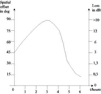
Here we
add a practical example to the spatial offset problem. In the chart below is
shown the spatial offset during a window EU-US. At US moonrise we have 45° offset / 3 dB of extra loss. At half of the window spatial turns to nearly 90° / >20dB of extra
loss. At Eu moonset the angle turns to below 30° / 1 dB loss. Here is the
best chance to place a sked if other parameters are fit as well. Europe to the northwest US
is much worse, for example my qth to KA7V in Oregon
is always >70° / >10dB loss. This makes it very hard for linear
polarized stations to complete a qso. Better is the
path EU to VK5 where spatial is always below 30° / 1dB loss. |
Moonrise US to moonset EU |
|
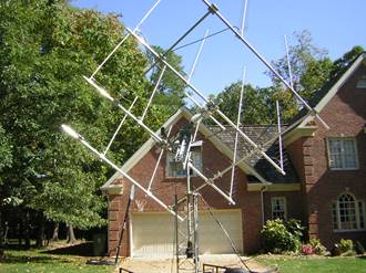
This antenna above shows how to solve the polarization problem. Or use
a dish ! |
N8CQ 16 yagi portable on trailer with pol.
rot. |
|
|
|
LibrationLibration in latitude variations have showed the greatest effect during the
tests from SV3AAF. Libration in longitude
variations (thin sine) have not showed significant effect. Anyway
for the most of 2009 they almost coincide so it will be more difficult to
distinguish for someone that does not have the experience of 2008. For the moment the most important: If you make some echo tests of your own for the
purpose of libration study please correlate your
observations also with lunar declination. At higher positive declinations I
expect more clear results of the libration effect
highs and lows. Perigee is of lesser relevance and it better be avoided for
the purpose of libration tests at second half of
2009 because it doesn’t coincide with high moon at northern hemisphere. Audio
spectrum waterfall monitor like Spectran can help
the observation always along with our good ears. Tnx to SV3AAF for this info !! Maybe all of us can check if this fits with own
observations. More theory at : http://en.wikipedia.org/wiki/Libration
|
|
|
|
|
|
|
|
Update August 2017
|
After we learned about the conditions
we will have a look to the station we will use for 432 EME. We have 3 major things to observe: Preamp & RX 2.1 sensitivity & gain of preamp 2.2 good IP3 & filter 2.3 high qrg stability for
dig. modes PA & Transmitter 3.1 Power 3.2 losses tx-ant 3.3 qrg & power
stability for dig. modes Antenna 1.1 Gain & SWR 1.2 Side lobes Losses dipol-relay Location 4. Simulation of your system Minimum
requirement for a qso in cw. So far
I know the smallest stations used so far were : I5TDJ
single long yagi 1K – EA3DXU 2x13wl &KW, both
were using a good preamp and more than one attempt. 4 yagi
to 4 yagi is always easy if pol. is cooperative. In
JT its possible to work with 30w and a single
medium yagi the bigger stations like 10 or 15m
dish. I would
like to hear what was the smallest station so far from little or medium sized
stations. Most
important is the antenna, but I will start with the preamps. 2.1 sensitivity & gain of preamp Like we
will see later on 432 we need sensitive preamps as close as possible to the
antenna. I will not go to deep into the well known
theory but the preamps have to fulfil following requests: Low
noise figure NF <0,5dB Good
Gain, G > 20dB depends on cable loss to RX High IP3
>10dBm Absolute
stable K>1 Maybe a
resonator in the input circuit to have a filter function This issue we will have a closer look to the preamp needed for EME. In all cases sensitivity is needed to hear well.
This is more valid on 432 & up due to colder background in the sky. The
best preamps I know are around 0,25dB. BUT when talking about absolute values
of noise figures we have to remember that the measurement error is nearly in
the same range!!! You need a good Noise figure meter and you have to know
what you are doing. If no expensive noise figure meter is available there is
only the chance to measure the performance in the antenna with sun noise or
other galactic sources. I will give some examples from the VK3UM simulation software with a single
21el. F9FT yagi. Sun flux =70, Tsky
= 30K, gain preamp 20dB.
We can
see that a low loss cable + preamp in front of an antenna can improve signal
like doubling the antennas. If all other parts are optimal a tenth of a dB at
the preamp makes not the big difference. But 10m RG213 will kill all
possibilities of a EME qso where small signals
expected. |
|
Which preamp is best ?? This
question has no answer which will fit every case. It depends on location and
your wallet. In an urban area you need all selection what is possible and IP3
must be good, NF is secondary. On a lonely island only
NF is interesting. And if you are able to use a soldering iron it can cost
20.-Eur, but you can pay up to several hundred euros for a commercial one.
The one I use today is from Hubert, DJ3FI a very fine cavity with <0,3dB
NF. Bandwidth is small and IP3 fair. Better IP3 have for example the DB6NT
preamps with ATF54.. series Transistors, but they
have wideband input. OZ2OE published in Weinheim some years ago a preamp with
ATF54143 which will cost only <20Eu. He used only a serial C input to Gate
and no tune. Simple and good, a bit difficult to handle self oscillation. The
production charges of the ATF are not always the same, so dependent on the
individual transistor you have NF will be 0,3 to 0,5. There
are of course many other preamps available. Google for preamp 432 and there
will be much info. Or look here : http://www.g0mrf.com/432LNA.htm http://www.ssbusa.com/db6ntvhfuhf.html http://www.qsl.net/dl5lf/432_preamp.html http://www.downeastmicrowave.com/PDF/70ulna.PDF http://www.rfham.com/
preamps http://www.kuhne-electronic.de/de/shop/143_Vorverstaerker Next
important point is the matching from the antenna to the preamp. If you
buy a preamp or the homebrew preamp is optimized at a noise figure meter the
best NF at the antenna can achieved only if the antenna has the same
impedance as the noise source, typical 50R. So not loose sensitivity the return loss of the antenna has to be 16dB or better (SWR
<1,4). Enough gain
of the preamp is recommended. Based on the example before, we change gain and
cable length. The NF
of the TRX 2dB, the gain of preamp is 20dB, cable preamp-TRX has a loss of
1dB. Now we change the values and see that with a 1 dB cable loss the gain
can be as low as 16dB to affect the noise figure.
Tuning. All OMs who have a noise figure meter I hope
know how to use, but for all other I have a very simple trick from OE3JPC.
All you need is your station with a FM RX an analogue ac-voltmeter and a very
small signal in band. The Voltmeter is connected to the audio out of the
transceiver. Use long wires that you can read the voltmeter while tuning the
preamp at the antenna. Tune the RX on a very small signal. Turn the antenna
into the “cold” sky and tune the preamp until the reading of the voltmeter is
minimum. (In german a better description is here: http://www.qsl.net/oe3jpc/eme/UHFTECH3.pdf Its very simple to optimize the preamp in the used
antenna, all problems due to mismatch (bad SWR) are solved this way. The only
disadvantage is, you optimize relatively, so no idea about the absolute noise
figure. This can be solved by measuring the sun noise or other noise sources
compared to the cold sky. Checking
absolute noise figure of the preamp with the sun. If there is no noise
figure meter, we can use easily the antenna and TRX as measuring system. We
need two things to measure, a good S-meter (or a chance to get the voltage
from the S-Meter) and a step attenuator. The measure function of the JT65
WSJT 4 fits not, because the demodulators of the receivers are often not
linear. The preamp must have enough gain so that the step attenuator does not
decrease the system noise figure. As we can see in the table above we need more than 20dB gain when a 10dB attenuator
is needed. (depends on estimated sun noise) With
the VK3UM EME planer (or other software) we can calculate where are
the cold sources and the sun are at a given time. Procedure
is to point the antenna first to cold sky (Aquarius, Leo or Pictor) and read
the S-meter (or better a voltmeter parallel to the s-meter). Then we point to
the sun and now we switch the step attenuator to the position that we get the
same s-meter reading as before. Now we see our sun noise on the step
attenuator. Because of local noise and (at high sun activity) various flux
values this should be repeated 3-5 times a day. With the mean value of these
values we should get close to reality.
The
same procedure can be made with the ground noise, but there are
several problems to solve. First is to have a dry non
conductive ground in your garden. It took me 3 years to find out that
my garden is wet and has a good conductivity. Good for 80m verticals, but
gives not the estimated ground noise values. Second is manmade noise, modern
plasma TVs switching power supplies make some more or less noise. So I found out, that my house wall is the best “ground
noise” when all PC & TVs are off. So instead pointing to the sun the
antenna is pointing into the ground or house wall with the full beam and we
get the ground noise. With
this to values measured carefully and some more times to get a feeling for
this we can calculate the RX parameters. Getting
own NF by two measures. The
VK3UM EMEcalc helps us to find out if the station
is ready for EME. For our example we take a single 21el. yagi
which is very popular in europe.
These
values we put in the VK3UM calculator. The last two needed values are a bit
difficult, spill over and feed thru. These names come from dishes and mean at
yogis’ side lobes and back lobes. The lobes give some extra noise to the
dipole and the system. We go into the datasheet of the antenna and see first
side lobe is 13dB down and the front/back ratio is >20dB. So we have up to 15K from the side lobe and about 5K from
the back. These values can be much higher in a noisy urban area!!! Now we
can calculate the
noise figure and gain of the system. For a 0,5dB preamp we have
to measure 5,6dB sun and 4,7dB ground. If not :
For the
two measured values we can calculate exactly gain & NF of the system when
all other parameters are fixed and known. So this
way shows how to find out the own parameters. With one yagis
the gain should be as it was taken from the datasheet, otherwise the antenna
has a problem. At bigger groups as 4 or more yagi
also the gain can be wrong by error in phasing lines. This should be found
out also by the method above. Simulation This
time I would show the possibilities of the simulation, so everyone can assume
what is possible to work with his station or check if all works fine. A good
tool is the VK3UM EMECalc. There are others of
course, but I believe Dougs software is the most
popular. Important: What we
get from the simulation is the absolute BEST value we can achieve. In
practical the achievements may reach the simulation only for a short time
under best condx. Not calculated is libration, absorption from the atmosphere and
polarization due to faraday. When used circ.pol. the polarization is not a
big problem, but on 432 and 144 MHz where most of the Hams using linear pol.
it’s a big problem. During low sun activities absorption is not seen for
longer and also faraday is not rotating so much. But in
real world you have to subtract from the calculated values a few dB. Like
all other simulations we need exact values to get good results. Following
values are needed, beginning at the left upper side. Tsky That’s
the background temperature of your cold sky. For 432 it is 20 or 25K depends
on which cold spot is visible for measuring, Aquarius 20K or Leo with 25K.
For EME contacts you have to put in the background temperature of the moon
out of the lunar calendar or VK3UM EME planner software. If you have no
elevation you have to put in your local outdoor temperature in Kelvin (K);
290K is the value for 17°C = 62F. In this
case the cold sky (C/S) to ground value is not valid and has to be zero. RxBW The RX
bandwidth has to be set to 2500 Hz at JT65 and to 120-50Hz in CW. In CW it
depends very on your ear-brain filter training, how small a CW signal can be
to decode the signals. DL9KR can decode small CW signals down to 50Hz or better,
while an untrained operator has 120Hz or more. Physical
theories are that the signal/noise ratio becomes better when the bandwidth
becomes smaller. Easy to understand your signal goes through the filter,
while the noise left and right of the filter is blocked. So
sum of noise is less with smaller filters and the signal is constant and so
the signal / noise ratio increases. When we hear small signals the ear-brain
uses biology’s filters to decode the CW. This can be trained and represented
as bandwidth of your ear-brain. Mesh
Diameter & Spacing Only
for dishes is Self-explanatory LNA
loss is the
sum of the losses between dipole and preamp, Baluns, connectors, dividers, cables
and relays. (more than you expect !! ) LNA NF noise figure of the preamp, can be worse by bad
SWR. Normally all preamps are tuned at a 50 Ohms system. So
if SWR is not too good NF can be less then measured. LNA
gain
Self-explanatory gain of the preamp in dB. All the
above values are zero if no preamp is used. Coax
loss with
preamp it’s Self-explanatory the loss between LNA and TRX b)
without preamp it’s the loss between Dipole and TRX RxNf is the NF of the TRX (Transceiver) Spill
over& Feed through I explained last issue. Then TX power and loss of TX
line has to be set and also the outdoor temperature and distance to the moon
(apogee or perigee). Yagi
Array The
last value will be the antenna gain. There it is easy to choose from a menu
well known types, but you can put in just a value from your own antenna.
Important to known that this software calculates always 2,85dB for doubling
antennas. This can be wrong when stacking distance is not the best. |